These photos of NASA (and its predecessor NACA) wind tunnels facilities are in a treasure trove of wonder at NASA’s public domain image archive. Taken between the 1920s and 1950s, the images reflect not only the huge scale of the space dream but also how everything about it dwarfs mankind and life on Earth.
The aircrafts were placed on posts and hit by air is accelerated through the tunnel by fans. The first tunnel was constructed in 1920 at the Langley Research Center in Hampton, Virginia, then under the auspices of the National Advisory Committee for Aeronautics (NACA). Some newer facilities use magnetism to suspend aircraft in midair.
16 Foot High Speed Wind Tunnel
Description(February 8, 1942) 16ft High Speed Wind Tunnel downstream view through cooling tower section.

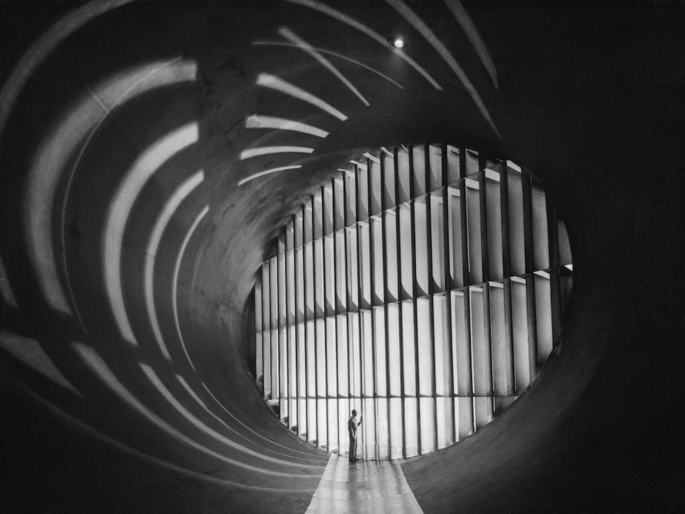
Abe Silverstein Supersonic Wind Tunnel
(C-1956-42059): This nozzle interior view shows the right sidewall distinctly curved and the left wall almost flat. Note the man’s shadow and multiple reflections in the polished walls.

6- x 6-Foot Supersonic Wind Tunnel
(June 1, 1948) A researcher inspecting a model in the 6- x 6-Foot Supersonic Wind Tunnel’s test section. Note the two circular schlieren windows, and that the vertical blade supporting the sting does not extend to the floor.
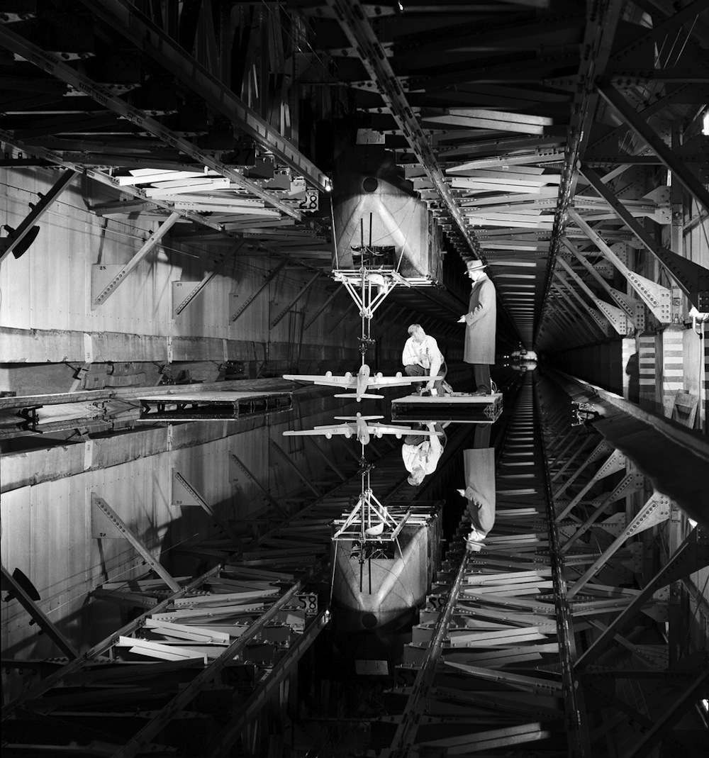
(1946) Boeing B-29 long range bomber model was tested for ditching characteristics in the Langley Tank No. 2 early in 1946.
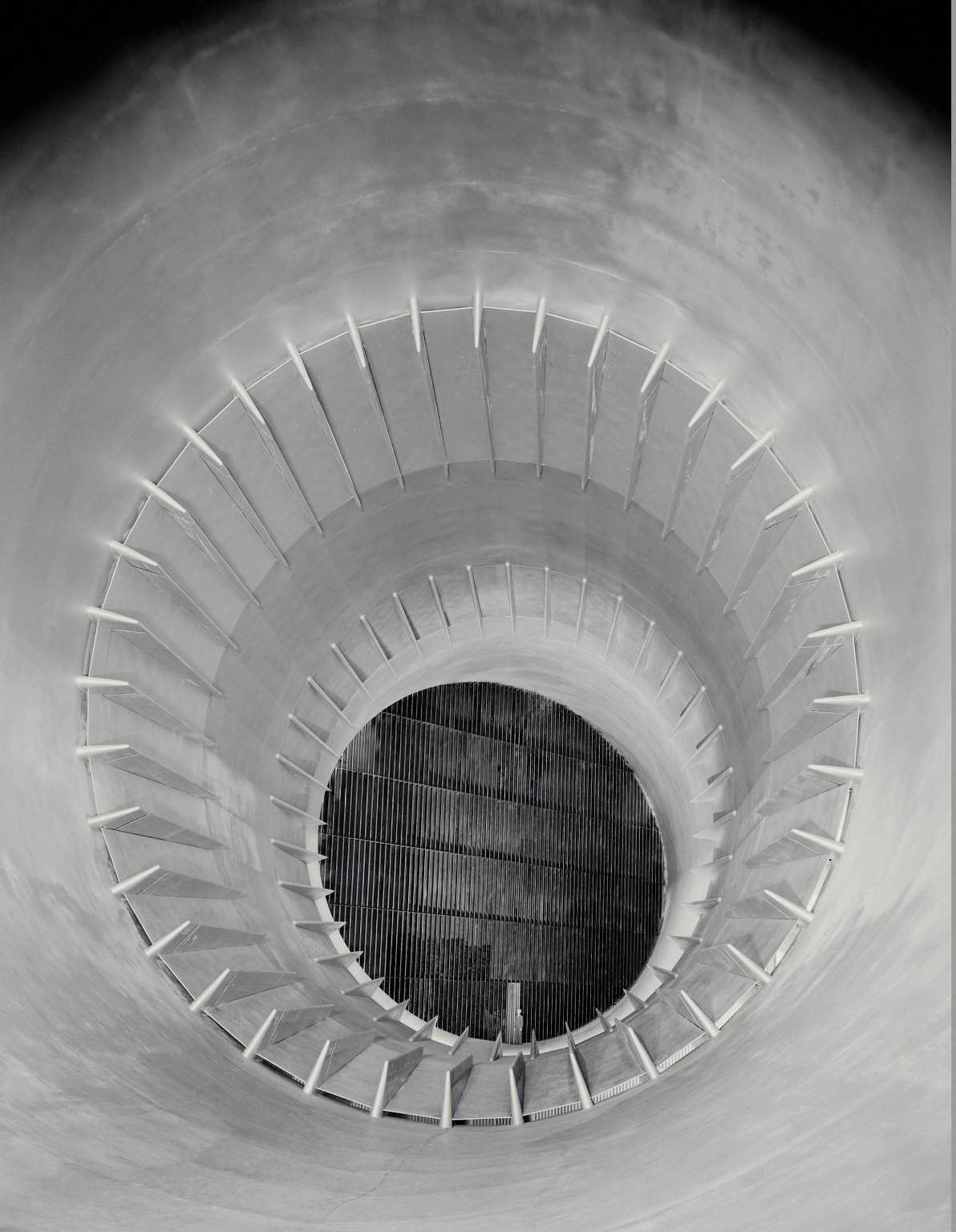
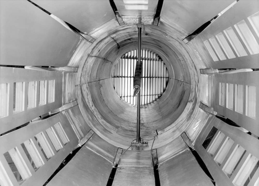
(March 15, 1950) Guide vanes in the 19 foot Pressure Wind Tunnel at Langley Aeronautical Laboratory, National Advisory Committee for Aeronautics, form an ellipse 33 feet high and 47 feet wide. The 23 vanes force the air to turn corners smoothly as it rushes through the giant passages. If vanes were omitted, the air would pile up in dense masses along the outside curves, like water rounding a bend in a fast brook. Turbulent eddies would interfere with the wind tunnel tests, which require a steady flow of fast, smooth air.
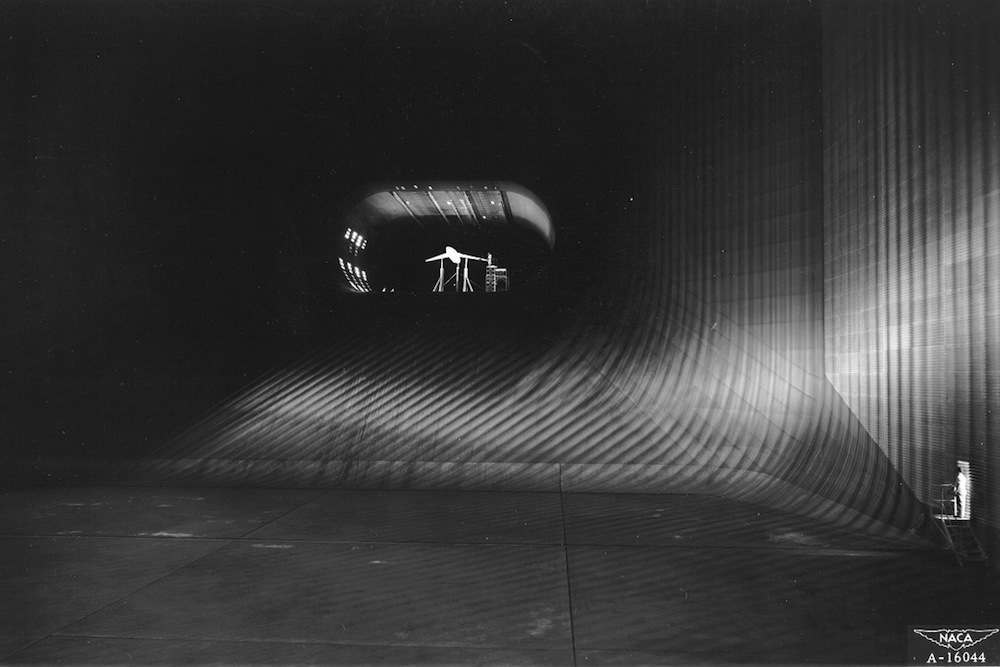
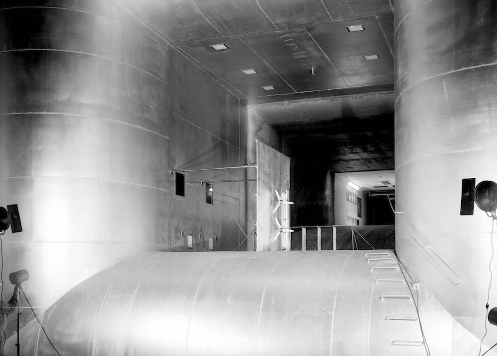
(1947) Looking down the throat of the world’s largest tunnel. The scene is NACA’s 40 x 80 foot wind tunnel at Ames Aeronautical Laboratory, Moffett Field, California, which when it was built was the world’s largest. The camera is stationed in the tunnel’s largest section, 173 feet wide by 132 feet high. Here at top speed the air, driven by six 40 foot fans, is moving about 35 to 40 miles per hour. The rapid contraction of the throat (or nozzle) speeds up this air flow to more than 250 miles per hour in the oval test section, which is 80 feet wide and 40 feet high. The tunnel encloses 900 tons of air, 40 tons of which rush through the throat per second at maximum speed. Dwarfed by the immensity of the tunnel structure, the experimental model seen here is actually almost 50 feet long. Embodying a sharply swept-back wing suitable for supersonic flight, it is undergoing tests designed to improve the landing characteristics of this type of airfoil. Mounted on struts connected to scales under the test section, it is “flown standing still” while each element such as lift and drag is measured and air pressures occurring across the wing are recorded. Information gathered from such tests were made available to the nation’s aircraft manufacturers by the NACA (now NASA), an independent agency of the U.S. Government.

Swinging Valve for Supersonic Wind Tunnel
Description (May 17, 1956) 24 foot diameter swinging valve at various stages of opening and closing in the 10ft x 10ft Supersonic Wind Tunnel.

Description (February 3, 1922) The Variable Density Tunnel arrives by rail from the Newport News Shipbuilding and Dry Dock Company. The Tunnel was installed at Langley.
(April 1, 1921) The National Advisory Committee for Aeronautics (NACA)’s first wind tunnel, located at Langley Field in Hampton, VA, was an open-circuit wind tunnel completed in 1920. Essentially a replica of the ten-year-old tunnel at the British National Physical Laboratory, it was a low-speed facility which involved the one-twentieth-scale models. Because tests showed that the models compared poorly with the actual aircraft by a factor of 20, a suggestion was made to construct a sealed airtight chamber in which air could be compressed to the same extent as the model being tested. The new tunnel, the Variable Density Tunnel was the first of its kind and has become a National Historic Landmark.
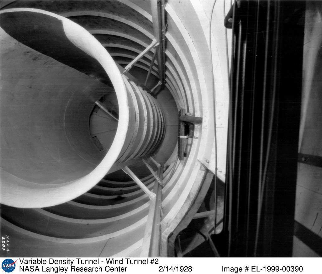
(February 14, 1928) View of the interior of the exit cone of the Variable-Density Tunnel (VDT) during its brief period of operation as an open throat design. After the fire, the VDT section engineers decided to convert the tunnel to an open throat design. Operations of the redesigned tunnel began in April 1928, however the engineers could not succeed in getting the new tunnel to operate properly and decided to return to the original closed throat design. The tunnel began closed throat operations in December 1930.
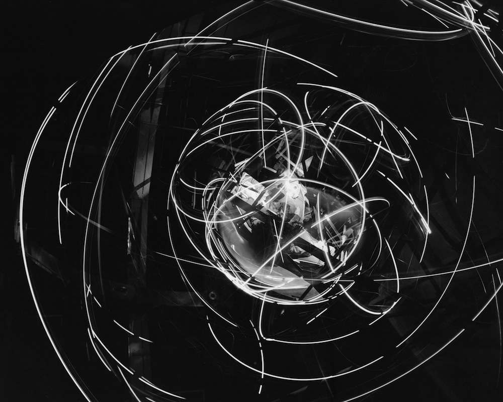
Project Mercury: AWT Gimbaling Rig Showing Motion
(December 16, 1959) This device is formally known as the MASTIF or Multiple Axis Space Test Inertia Facility and is located in the Altitude Wind Tunnel. It was built at the Lewis Research Center, now John H. Glenn Research Center, and designed to train astronauts to regain control of a tumbling spacecraft. This sure looks like fun, huh?

20-Inch Supersonic Wind Tunnel
(P-1265): With one side open for access, the flexible top and bottom of the 20-Inch SWT’s nozzle and the actuating rods can easily be seen.
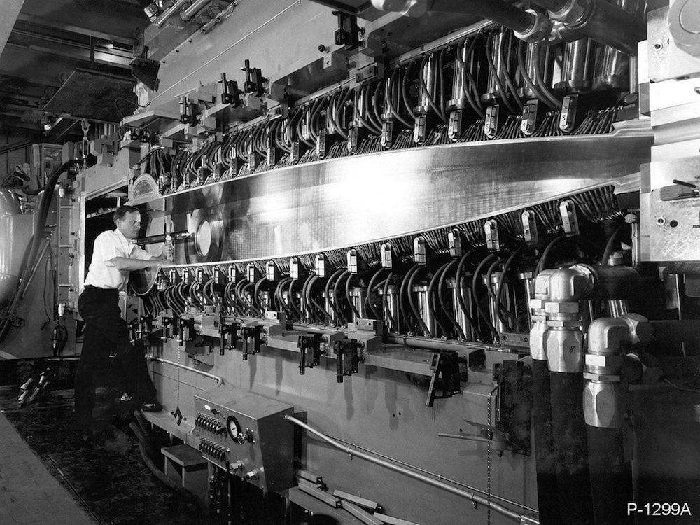
21-Inch Hypersonic Wind Tunnel
(P-1299A): The HWT’s nozzle and test section, including the jack system that contoured the top and bottom walls are visible with one side retracted. Note the side wall hanging from the monorail at far left.
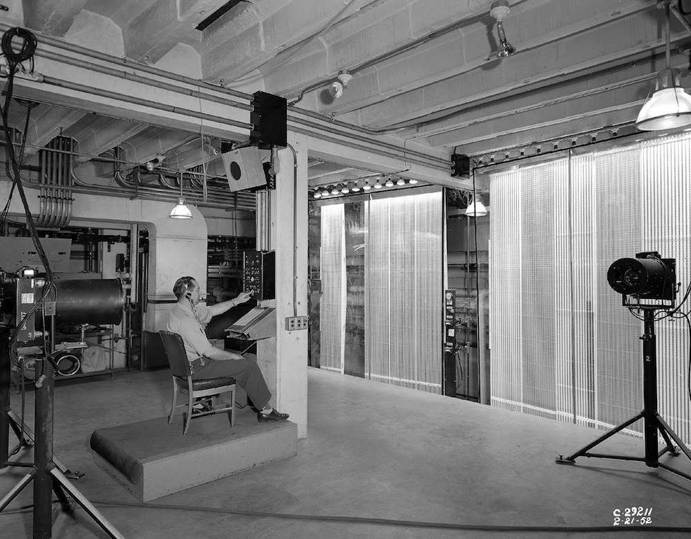
8×6-Foot Supersonic Wind Tunnel
(C-1952-29211): The 8 x 6 SWT had the most modern data acquisition and data processing equipment available when it opened, and its capabilities have been upgraded numerous times. Early data acquisition equipment included a telereader to optically record manometer panel data .

8×6-Foot Supersonic Wind Tunnel
(C-1949-23277): The stator case of the 8 x 6 SWT’s seven-row compressor can be opened for inspection and maintenance. Three electric motors totaling 87,000 horsepower turn it. Note the toriod-like screen at the compressor’s inlet.
Abe Silverstein Supersonic Wind Tunnel
(C-1956-42059): This nozzle interior view shows the right sidewall distinctly curved and the left wall almost flat. Note the man’s shadow and multiple reflections in the polished walls.
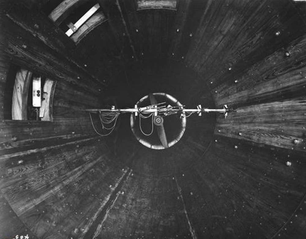
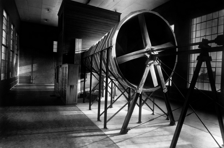
Variable Density Tunnel
(L-405): This interior view of the VDT, taken shortly after it opened in 1922, looks downstream. Note the wooden construction, the propeller in the background and the observation windows. These windows aligned with small portholes in the pressure shell.
8-Foot High-Speed Tunnel
(1957-L-00959): The later slotted-wall test section of the 8-Foot HST. Note the curved re-entry baffle at the end of each slot and the turning vanes in the background. The turning vanes were original equipment.
7×10-Foot Low-Speed Wind Tunnel
(1957-L-01191): This unusual view looks through both test sections of the modified 7- 10-Foot LSWT, with the 15.8 x 17-foot test section in the center and the original 7 x 10-foot test section in the distance.
Would you like to support Flashbak?
Please consider making a donation to our site. We don't want to rely on ads to bring you the best of visual culture. You can also support us by signing up to our Mailing List. And you can also follow us on Facebook, Instagram and Twitter. For great art and culture delivered to your door, visit our shop.